Engineering Drawing Title Block: What to Include and Why It Matters
A practical guide to title blocks on engineering drawings — what fields to include, layout options, common mistakes, and how to get them right.
The title block is one of the first things a manufacturer, inspector, or colleague looks at when they pick up a drawing. It tells them what they’re looking at, who made it, what revision they’re holding, and what standards apply.
Get it wrong — or leave it incomplete — and you create confusion downstream. Parts get made to the wrong revision. Material callouts get missed. Approval chains are unclear.
This guide covers what goes into a title block, the main layout options, common mistakes, and the choices I made when designing the title block for ClearHandoff’s drawing tool.
What is a title block?
A title block is a bordered area on an engineering drawing that contains identifying and reference information about that drawing. It’s standardized by ISO 7200 (international) and the ASME Y14 series (US), though most companies adapt the standard to their needs.
Every drawing should have one. It’s not decoration — it’s metadata that makes the drawing usable.
What goes in a title block?
There’s no single “correct” set of fields, but the following covers what most mechanical engineering teams need:
Identification
- Drawing title (name) — What the part or assembly is. Should be specific enough to distinguish it from similar drawings.
- Drawing/part number — The unique identifier. This is how anyone — whether a colleague, supplier, or your PLM/ERP system — finds and references this drawing.
- Revision — Which version of the drawing this is. Typically a letter (A, B, C…) or number. Critical for manufacturing — you need to know you’re building to the latest release.
Approval and traceability
- Drawn by — Who created the drawing.
- Drawn date — When it was created or last revised.
- Approved by — Who reviewed and released it. This is the person accountable for the drawing’s correctness.
- Approved date — When it was approved.
Manufacturing information
- Material — What the part is made from (e.g., “AISI 304”, “Al 6061”, “POM”). Manufacturers need this before they can quote or plan production.
- Scale — The ratio between the drawing and the real part (e.g., 1:1, 2:1, 1:5). Important for anyone trying to visually gauge proportions.
- Unit — Millimeters or inches. Never assume. Always state it.
- Mass — The expected weight of the part. Useful for shipping, structural analysis, and assembly planning.
- General tolerances — The default tolerance class that applies to dimensions without explicit tolerances (e.g., ISO 2768-m).
- Surface finish — The default surface roughness requirement (e.g., Ra 3.2).
- Projection method — First-angle or third-angle projection, shown with the standard symbol. This tells the reader how to interpret the views.
Administrative
- Company name — Who issued the drawing. ISO 7200 calls this field “Legal owner.”
- Sheet number — “Sheet 1 of 3” — essential for multi-sheet drawings.
- Format — The paper size (A4, A3, etc.).
Not every drawing needs every field. Which fields make sense depends on the drawing type — a detail drawing of a single part benefits from material, mass, and surface finish fields, while an assembly drawing might need a parts list reference instead. A quick internal sketch might only need a title, date, and revision. But for anything going to manufacturing or a customer, most of these fields earn their space.
Title block placement
ISO 5457 defines the title block position as the bottom-right corner of the drawing, and that’s overwhelmingly what you’ll see in practice. Some companies extend the area around it with additional elements — a revision table along the bottom edge, a parts list above it (on assembly drawings), or extra note fields — but the title block itself stays in that corner.
You’ll also occasionally see a tall, narrow block running up the right edge — this is more common in architecture and construction than in mechanical engineering. It works well on large-format sheets that get rolled or hung in plan racks, but it’s unusual for standard mechanical drawings.
For most mechanical engineering work on A4 and A3, stick with the ISO 5457 bottom-right corner block. It’s compact, conventional, and puts information where people expect to find it. This is my personal recommendation, shaped by training in Germany and experience in the US. If you work primarily within ASME or GB/T conventions, your setup will look different — more on that in the next section.
Regional standards: Europe, North America, and Asia
Title block conventions aren’t universal. If your drawings cross borders — especially to manufacturing partners — it’s worth knowing the differences.
Europe follows ISO 7200 (and its national adoptions like DIN EN ISO 7200 in Germany). First-angle projection is standard. Title blocks tend to be compact and structured, with metric units and ISO tolerance references (e.g., ISO 2768-m). This is the convention I grew up with as an engineer trained in Germany.
North America follows the ASME Y14 series (including Y14.1 for sheet sizes and Y14.100 for drawing practices). Third-angle projection is standard. Title blocks often include more legal and contractual language — distribution statements, export control notices, proprietary warnings — driven in part by defense and export control requirements. Sheet sizes follow the ANSI system (A through E) rather than ISO A-series.
China (GB/T) follows its own national standards (GB/T 10609.1 for title blocks), which cover similar ground as ISO 7200. First-angle projection is standard. Title blocks are often bilingual (Chinese and English) when drawings are intended for international use. Given that China is the world’s largest manufacturing base, many Western companies encounter GB/T-formatted drawings when working with Chinese suppliers — or need to produce drawings that Chinese manufacturers can read without ambiguity.
Japan (JIS) follows its own national standards (JIS Z 8311 for drawing sheets, JIS B 0001 for mechanical drafting) with third-angle projection — making it a notable exception among Asian countries.
The practical takeaway: if you’re sending drawings to manufacturers in different regions, always include the projection symbol, always state the unit, and consider whether your title block fields will be understood without cultural context. A material callout like “1.4301” is clear in Europe but means nothing in the US — where the equivalent is “AISI 304.”
The choices I made for ClearHandoff’s drawing tool
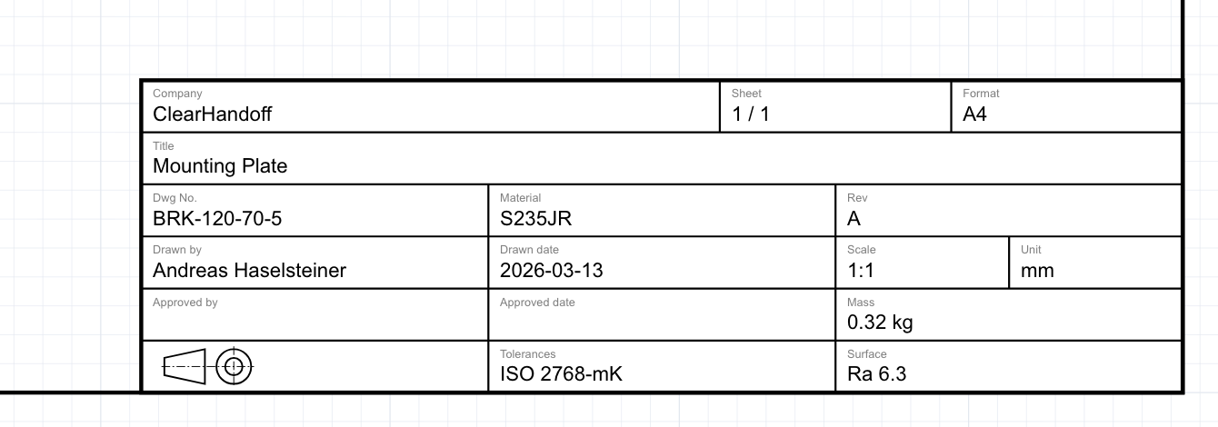
I’m a mechanical engineer trained in Germany, and I taught technical drawing at University of Bremen. When I built the title block for ClearHandoff’s online drawing tool, I drew on that experience to decide on the standard block we use in the software. Here’s what I went with and why.
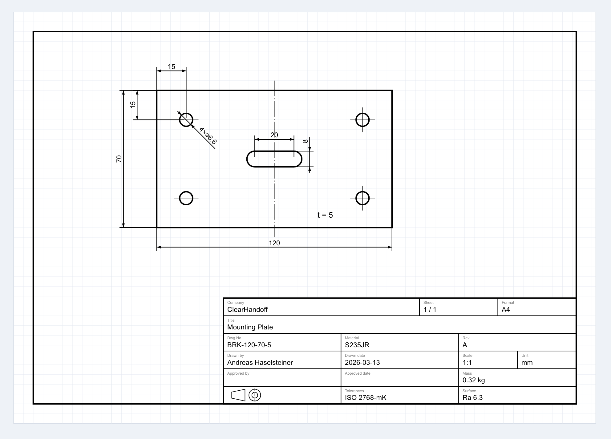
Layout: bottom-right corner, 180 × 54 mm. This is closely based on ISO 7200, though not a strict implementation — for example, ISO 7200 uses the label “Legal owner” where we use “Company”, and “Creator” where we use “Drawn by.” We also omit the “Document type” field that ISO 7200 lists as mandatory. I wanted to keep things simple and took inspiration from what I’ve seen in common practice as much as from the standard itself. The block is compact enough that it doesn’t dominate an A4 sheet — which matters on the most common paper sizes.
Six rows, structured by purpose:
- Company, sheet number, format
- Drawing title (full width — titles need space)
- Drawing number, material, revision
- Drawn by, date, scale, unit
- Approved by, date, mass
- Projection symbol, general tolerances, surface finish
17 fields total. ClearHandoff’s drawing tool currently focuses on detail drawings of individual parts, so the field selection reflects that — material, mass, surface finish, and general tolerances all belong here. An assembly drawing would need a different set of fields. I included what I’ve seen engineers actually need in practice for detail drawings: part identification, revision tracking, material and surface specs for manufacturing, and a clear approval chain. I deliberately left out fields like legal disclaimers, project codes, or customer-specific reference numbers — things that vary wildly between companies and bloat the block without helping the person reading the drawing.
Opinionated defaults. The tool starts with revision “A”, today’s date, scale 1:1, and millimeters. You can change everything, but sensible defaults mean you’re not filling in boilerplate every time.
In the future, we’ll likely let users configure the title block layout for their company. But starting with one well-considered default is better than starting with a blank canvas and no guidance.
Common title block mistakes
Having reviewed hundreds of engineering drawings — both manually and through ClearHandoff’s AI review — these are the mistakes I see most often:
Missing fields
The most common issue. The drawing has a title block, but half the fields are empty. No material callout. No general tolerance. No author in the “drawn by” field. Each missing field is a question someone downstream has to ask — or worse, guess at.
Outdated revision
The title block says “Rev A” but the drawing has clearly been modified since the initial release. This usually happens when someone edits the geometry but forgets to bump the revision. It’s a small oversight that can cause real manufacturing problems.
Inconsistent format across a team
Engineer A uses one title block template, Engineer B uses another, and the intern created their own from scratch. When drawings from the same company look different, it looks chaotic and makes review harder. Standardize on one template.
Wrong or missing projection symbol
First-angle and third-angle projection produce different view arrangements from the same 3D part. If the symbol is missing or wrong, every view on the drawing becomes ambiguous. This is especially important when drawings cross borders — first-angle is standard in Europe, third-angle in North America.
Scale not matching the actual output
The title block says “1:1” but the drawing was printed at “fit to page.” Now nothing measures correctly with a scale ruler. If you change the print scale, update the title block — or add “DO NOT SCALE” prominently.
How ClearHandoff checks your title block
When you upload a drawing to ClearHandoff, the AI review automatically checks the title block for completeness. It flags:
- Missing or empty fields that should be filled (material, tolerances, drawing author)
- Missing projection symbol
- Inconsistencies between the title block and the drawing content
It’s a first-pass check — the kind of thing a senior engineer spots quickly when they’re paying attention, but that’s easy to miss in a busy review.
If you’re creating drawings from scratch, ClearHandoff’s online drawing tool includes a built-in title block that follows the structure described above. Fill in the fields in the sidebar, and they appear on the drawing — no template setup required.
Sources
- ISO 7200:2004 — Technical product documentation — Data fields in title blocks and document headers — the official ISO standard for title block content
- ISO 5457:1999 — Technical product documentation — Sizes and layout of drawing sheets — the ISO standard that defines drawing sheet sizes and title block placement
- ASME Y14.1 — Drawing Sheet Size and Format — the US standard for drawing sheet sizes and layout
- Engineering Graphic Transition in Third-Angle and First-Angle Projection (Yang, 2011) — notes that the Chinese National Standard of Technical Drawings prescribes first-angle projection
- Third Angle Projection — Musashino Art University — confirms that JIS stipulates third-angle projection for product fabrication in Japan
- ISO 7200 on Wikipedia (German) — the German Wikipedia article includes a useful overview of mandatory and optional fields; the English Wikipedia article does not cover this in the same detail